Designing PCB cases
Written by: Person20020/Koji
Designing a nice case for your PCB projects can be the thing that takes it from something that looks like a cool idea to a well polished project that is ready to ship.
I am using KiCad and Fusion in the example but other software will be pretty similar. If you can’t figure anything out, searching the internet is a great way to start or you can ask in the Hack Club slack! (#Hardware or the current hardware YSWS channel might be good places.)
Prepare Your PCB
Section titled “Prepare Your PCB”The most helpful thing that I have found is having a good model of your PCB to design around. Many footprints in KiCad already have a model but for custom footprints that you have imported or those that are less common you may need to add your own.
Probably the best resource for models like this is the Grabcad library. It has a ton of detailed models of all sorts of parts. It is user contributed though so you should check dimensions with the datasheet. If you can’t find a good model online, you can also look at the datasheet and model them yourself.
Once you have your models, go through each footprint and assign it. Tiny parts like SMD resistors or capacitors are fine to ignore but anything that is large enough to impact the design of the case should ideally have a model. (Make sure to include stuff like connectors and buttons where the positions will be important in your design.)
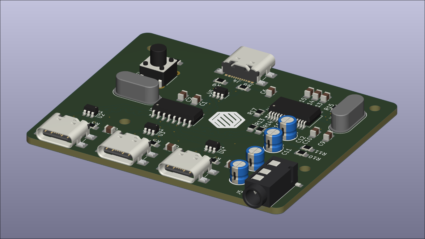
You can then export your PCB. Make sure that you include the board body and the components. If your PC is isn’t very powerful you can exclude all of the conductors and silkscreen to keep the model simple.
⇩⇩ More detailed instructions ⇩⇩
This section will be kind of like a beginners guide with more detailed step by step instructions.
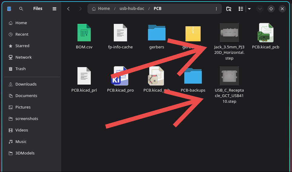
- Collect all of your models. You can go through all of you major components in your pcb and search for the name on grabcad.com/library or in google. Put them all in the PCB project folder so that they are included in the project path.
- In the PCB editor assign the models to the footprints.
- Select a footprint that needs a model assigned to it.
- Right click it, click
Properties..., and go to the3D Modelstab.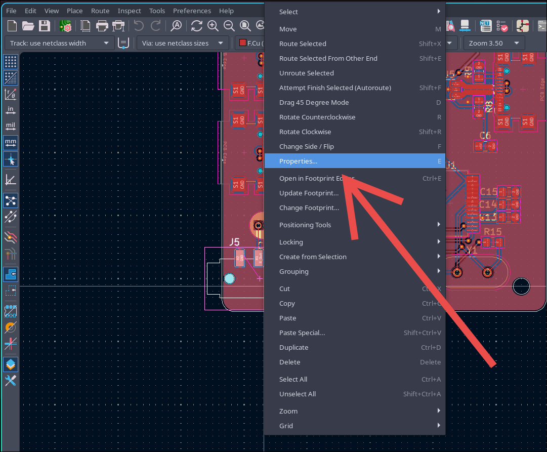
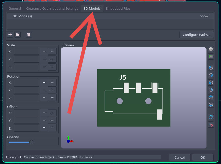
- Click the button with the folder icon.
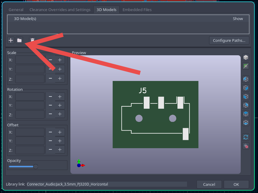
- Select the model for that footprint.
- If necessary adjust the rotation and offset settings to align the model with the footprint.
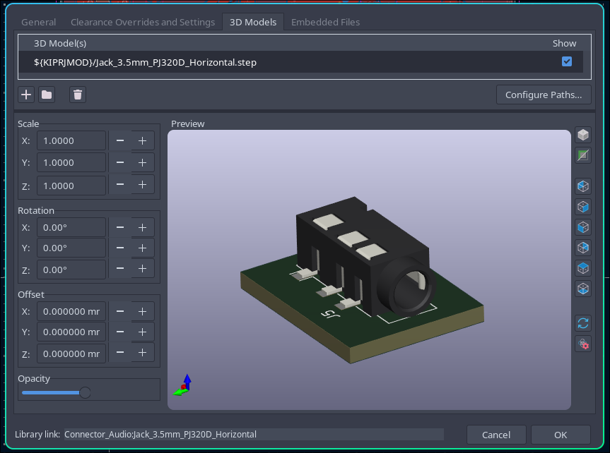
- Click
OKto save.
Do this for all footprints that need a model.
Design the Case
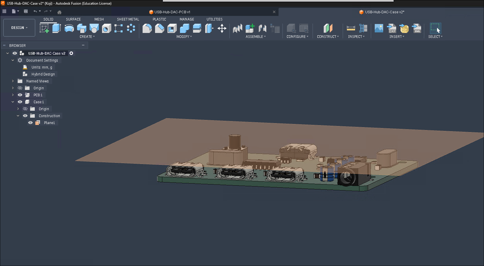
Section titled “Design the Case”First import the PCB into your CAD program. In FreeCAD you can drag and drop the step file but in Fusion 360 you can use File -> Upload. In Fusion this will import the step file as a bunch of individual parts so it can be helpful to do the following to put it inside of a component:
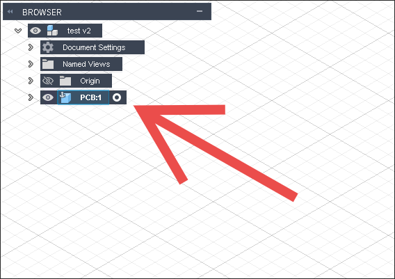
- Create a new file
- Create a component and save the file (Make sure the component is activated. It should have a dot next to it like this.)
- Go back to the first file
- Select everything
- Click
Create -> Derive - Set destination to ‘Existing Design’
- Click ‘OK’ and select the other file you created
This will put everything in the component in the new file.
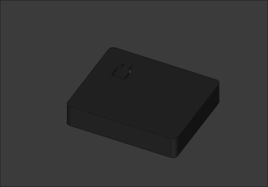
Once you have the PCB you can start on the case. For simple projects where the case is just an enclosure for the PCB (maybe some buttons, a display, connectors, or things like that) it can be easiest to start by making a simple box shape and then add detail after.
This was my process:
- Start with a basic shape enclosing the whole PCB
- Make important features like cutouts for connectors and the push button
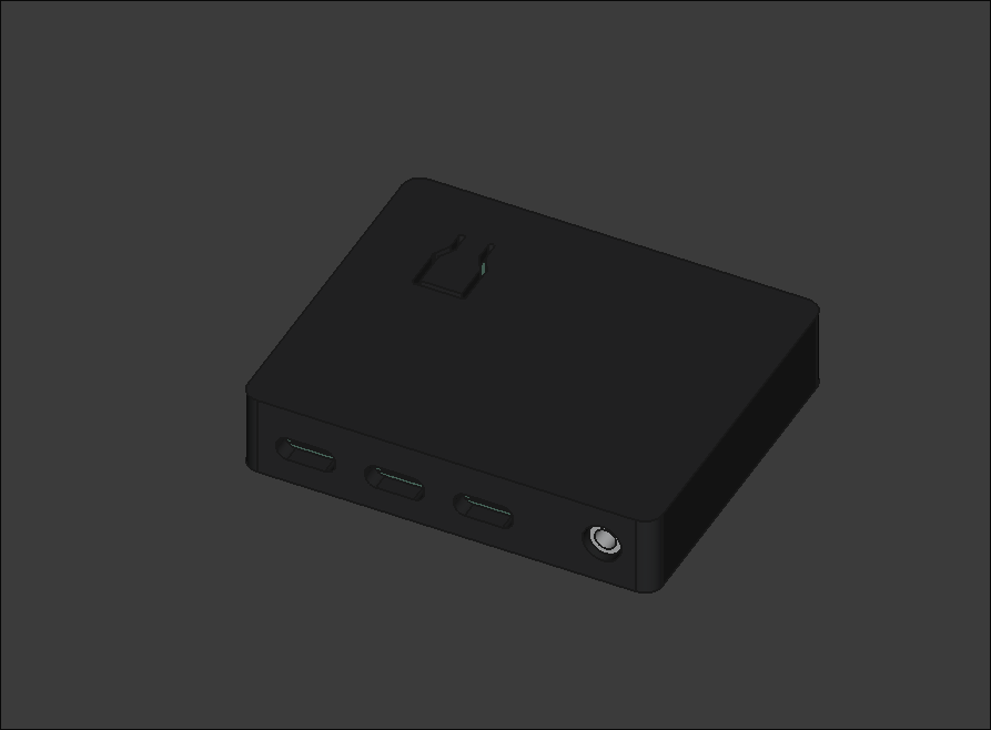
- Clean up the features - Add cutouts for clearance, fillets, chamfers, etc.
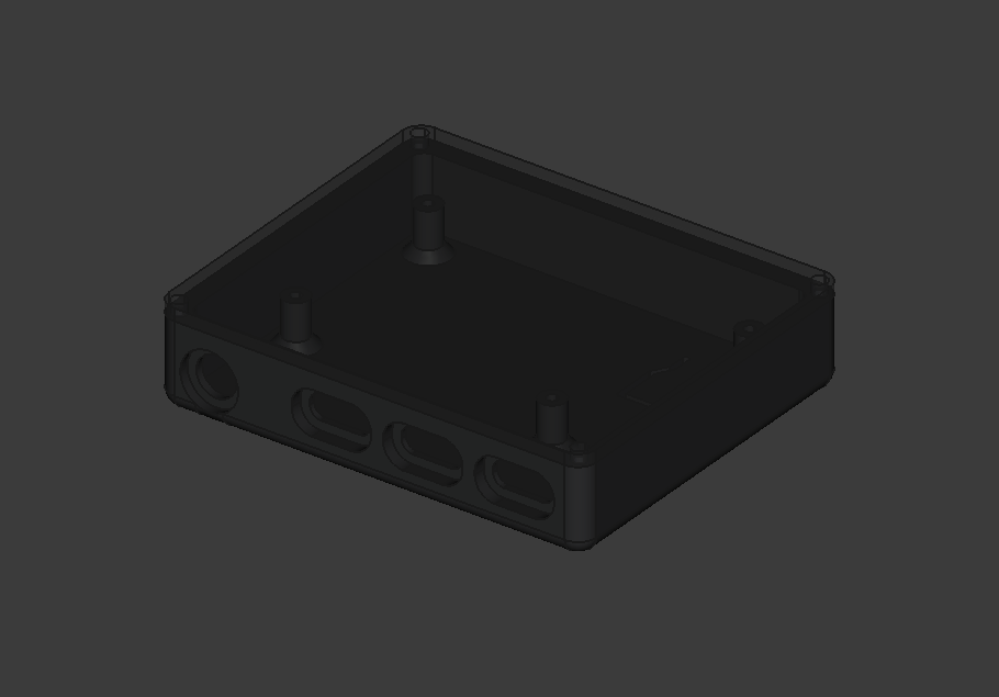
- Add mounting - Add printed standoffs (or something else) to hold the PCB in place and screw holes to keep the case closed.
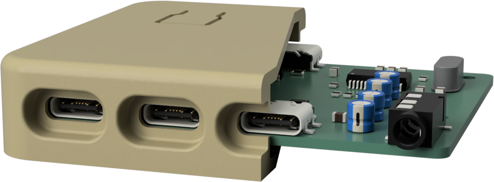
An example video of designing a case for a USB hub at 8x speed. I forgot to add a hole for the port on the back but it is the exact same process.
For mounting there are a few ways of doing things. In this example I used printed standoffs built into the case with an undersized hole to screw an m2 screw directly into.
These are some methods you can try:
- Threading screws into printed standoffs
- Heat set inserts or metal standoffs if you need it to be more durable
- Plain old nuts/bolts
- Printed clips/brackets/mechanisms (if done well these can be really nice and make it easy to work with)
- Hot glue for non mechanical parts (stuff that just needs to be stuck somewhere to stop it from moving). It is still usually good to have a recess or something to help position things well.
The mounting method you choose will depend a lot on the constraints of your design. (e.g. do you care about screw holes? do you have space for heat set inserts?)
⇩⇩ More detailed instructions ⇩⇩
This section will be kind of like a beginners guide with more detailed step by step instructions on how to actually design it.
Simple Enclosure
Section titled “Simple Enclosure”Let’s start with the simple enclosure:
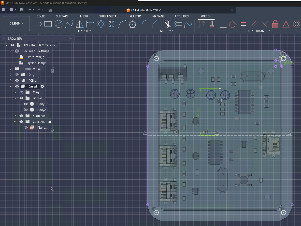
- Create a plane that is offset from the xy plane to the inner height of the case. In my cases this was to just above the top of the button but make sure that you will have enough clearance for all of your components.
- On that plane create a new sketch. Use the
Projecttool to add the outline of the PCB as construction lines/arcs. Use the offset tool to to create a new outline with a distance of 0.5mm (a bit of clearance so that the PCB has a bit of extra space). Then create another offset on the new outline with a distance of 4.5mm (you can make it thicker/thinner if you want but this is just about thick enough to fit m2 screws in the corners) for the wall.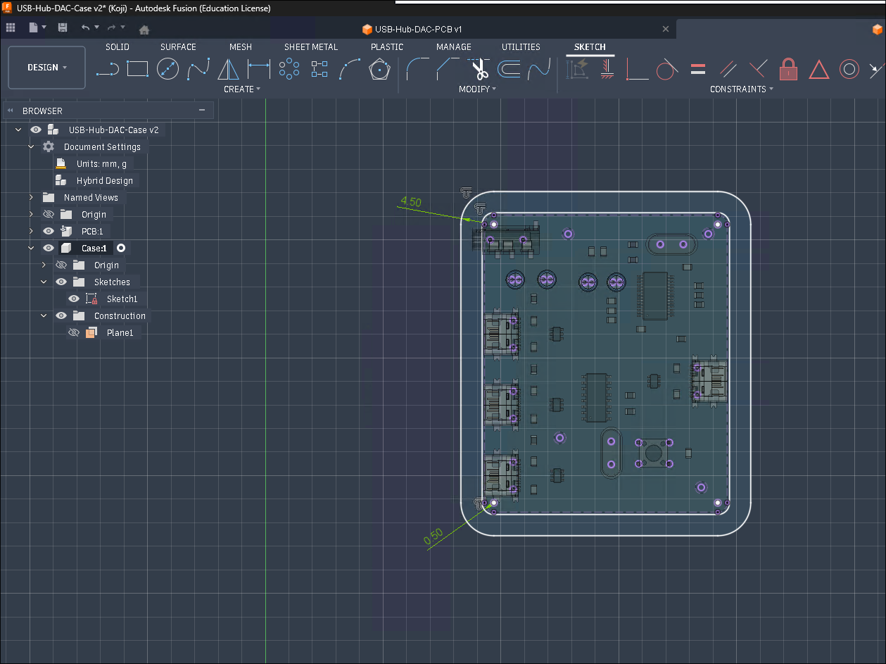
- Finish the sketch and extrude both the outer wall and the inner area upwards (away from the PCB) by 3mm.
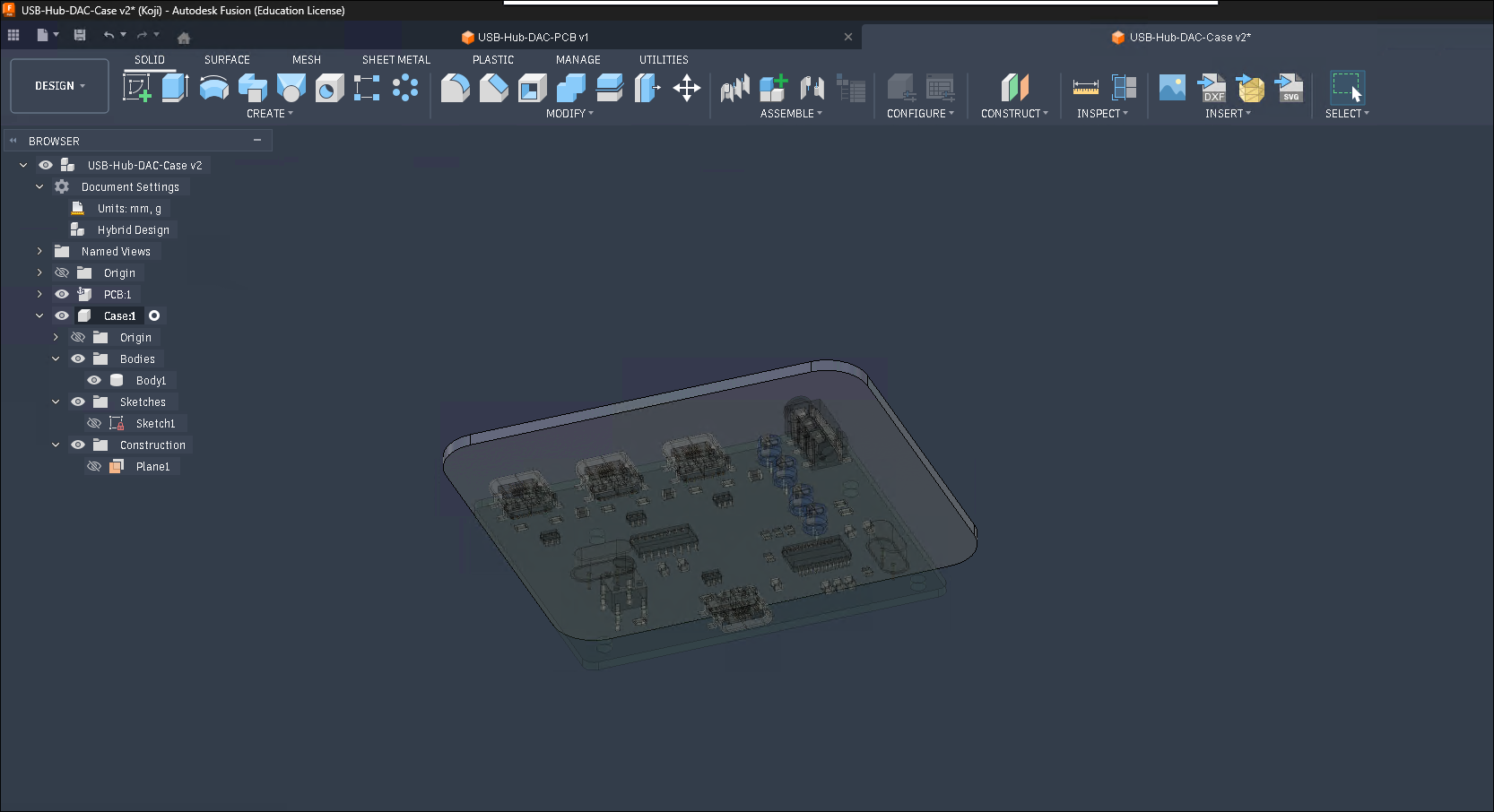
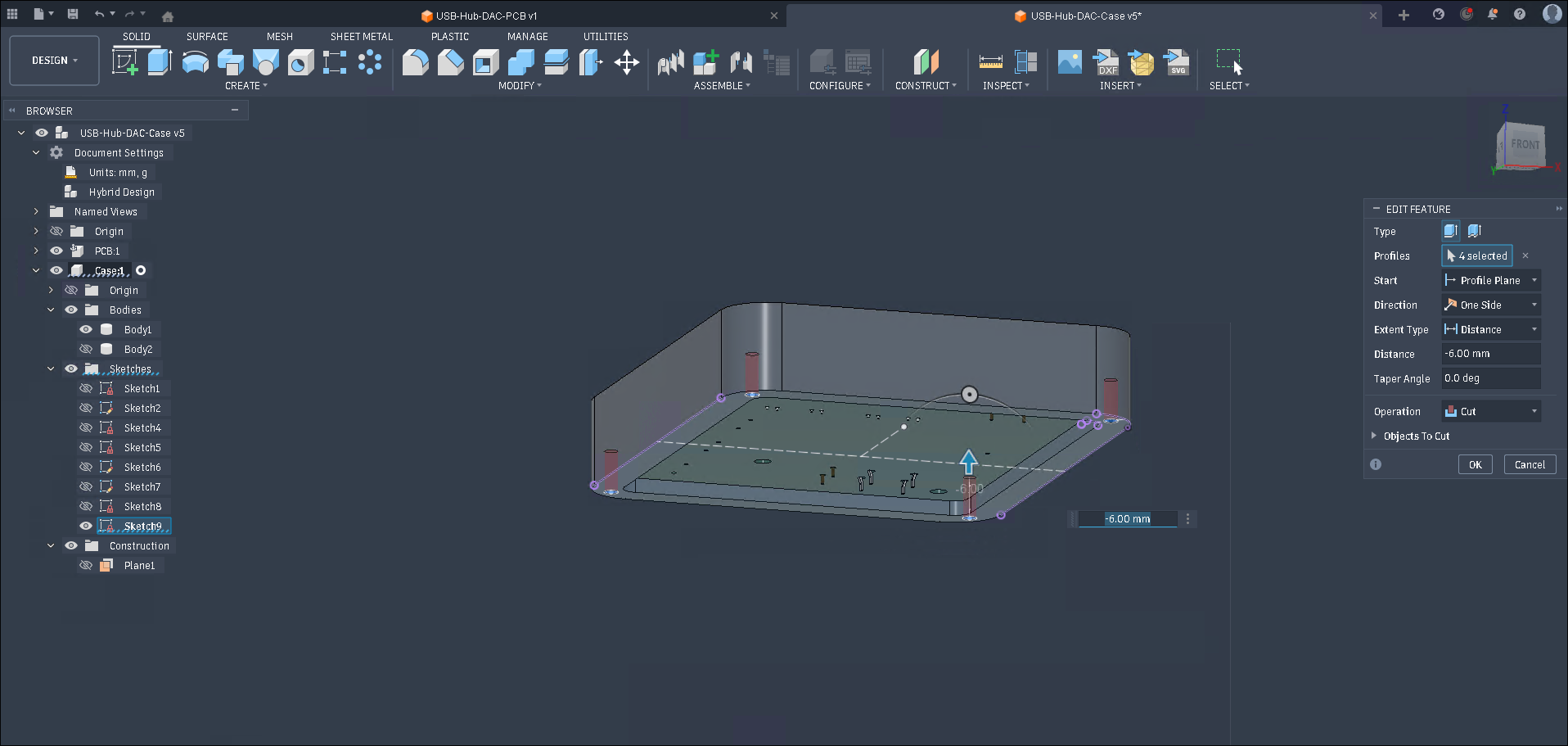
- Extrude the wall downward ~3mm past the PCB (you can use the
To Objectoption and add an offset of 3mm). The extra space is for the heads of screws that will hold the PCB in place (in this case m2 screws).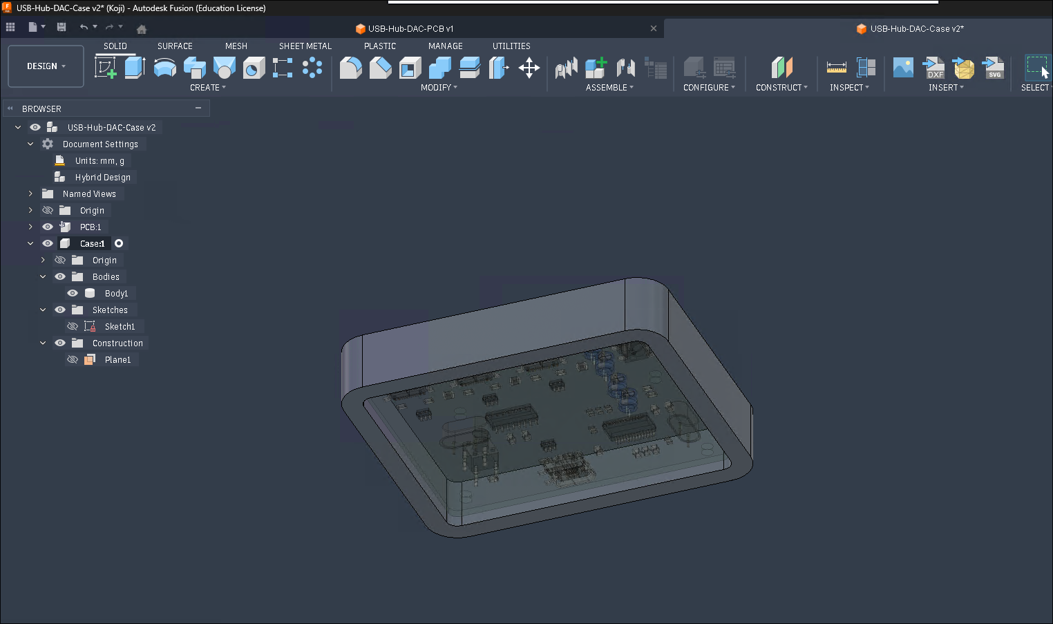
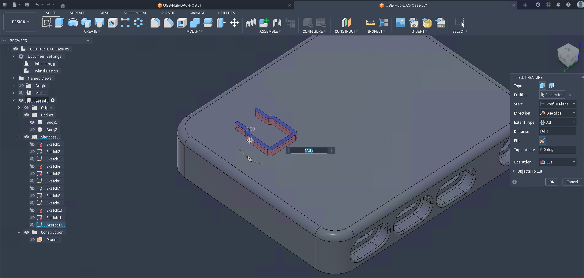
- Create a new sketch on the bottom of the top piece. Add screw holes. With the thickness of the walls at 4.5mm you can fit a 1.9mm hole to screw an m2 screw directly into the plastic. For the first hole I made a line between the inner and outer edges of the corner and then attached the circle to the center point. I then mirrored it across two construction lines in the center (because this is a simple rectangular shape). Finish the sketch and extrude the holes up by ~6mm (or longer depending on how long of screws you plan to use.)
- Create another sketch on the bottom of the top piece. Use the
Projecttool to add the outline and add 2.5mm screw holes centered on those from the top (this way the screws can spin freely while going through this part and are easier to put in). Finish the sketch and extrude it by 2mm. (Make sure to set the operation toNew Body.)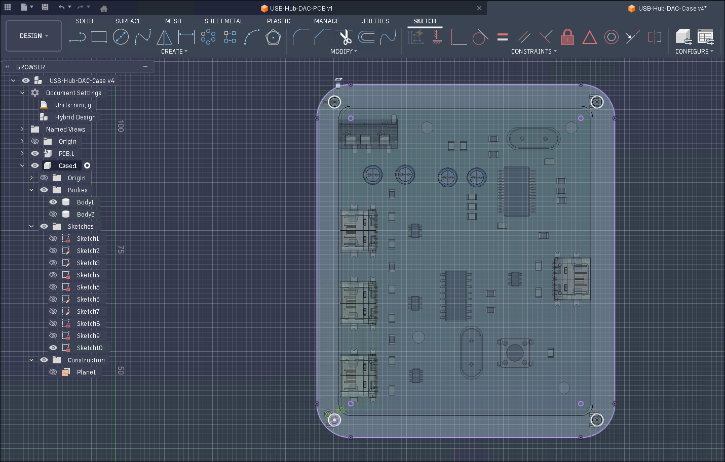
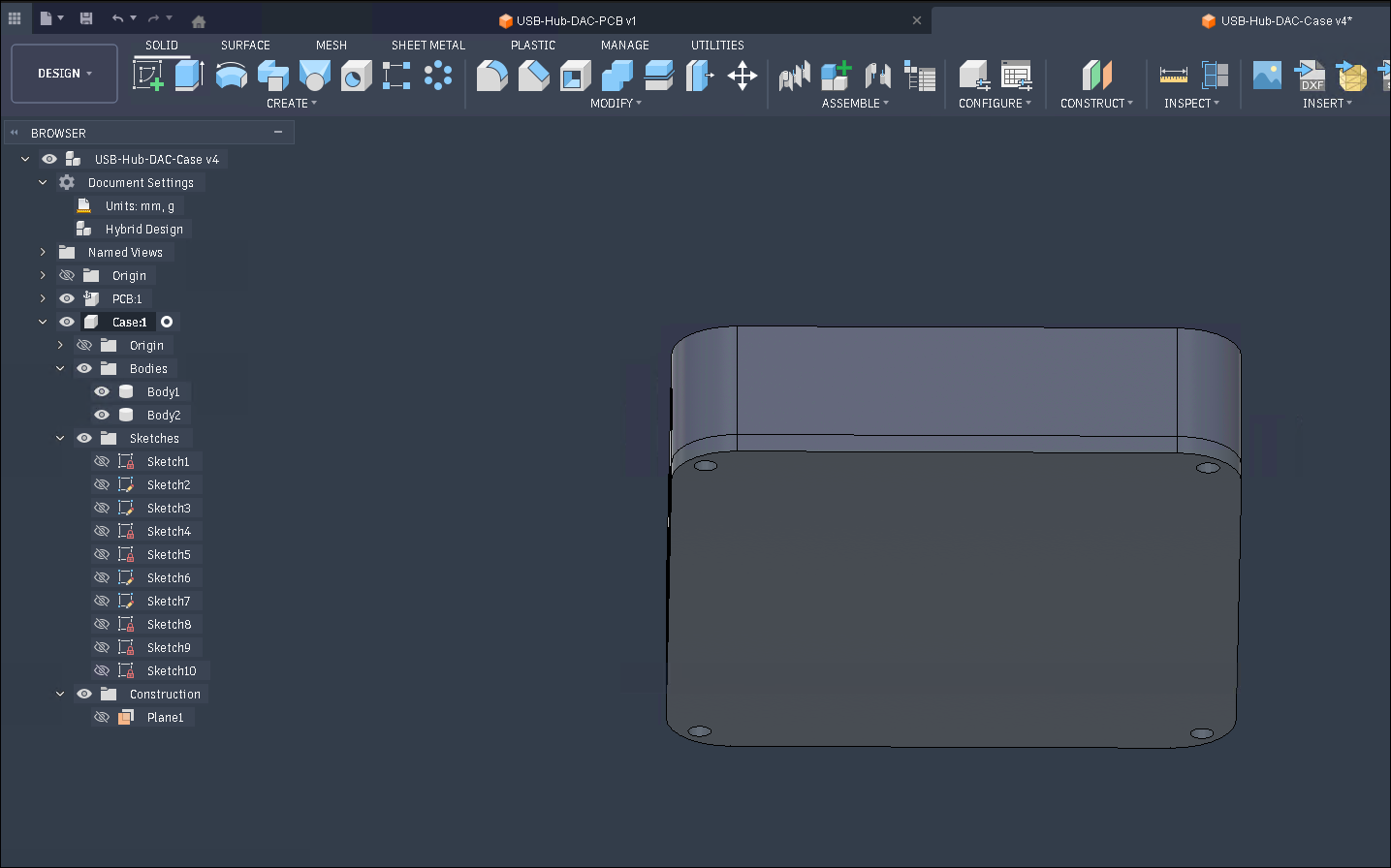
Now we are done with the basic enclosure!
Connectors/Other Features
Section titled “Connectors/Other Features”Next we will add some other important details. Here I will be adding the cutouts for USB ports.
- Create a sketch on the face where you need the cutout. I will be starting with the USB ports. You can then hide the case and use the
Projecttool to add the outline of the port. Create an offset line with a distance 0.5mm. (This is to add a bit of extra clearance for 3D printing.) Finish the sketch and then extrude it. You can use theTo Objectextent type to make the extrude go only through the wall. This is the main through hole.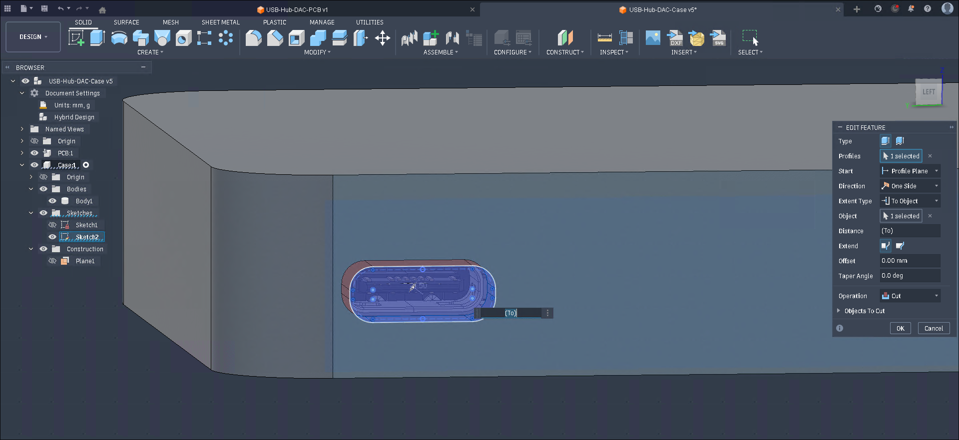
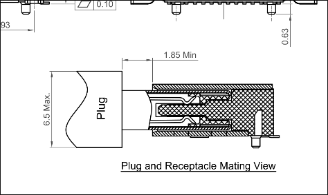
- Now create another sketch on the same face and create an offset of the previous hole. This is for the wider part of the connector. Most USB C cable connectors have a max size of 6.5x11.5mm so I will be using a hole that is 13mm wide. Finish the sketch and extrude as a cut. The connector I am using has a 1.85mm gap between the front of the connector (the female one on the PCB) and the plastic part of the connector on the cable so I will be leaving 1mm of material by using
To Objectand an offset of -1mm.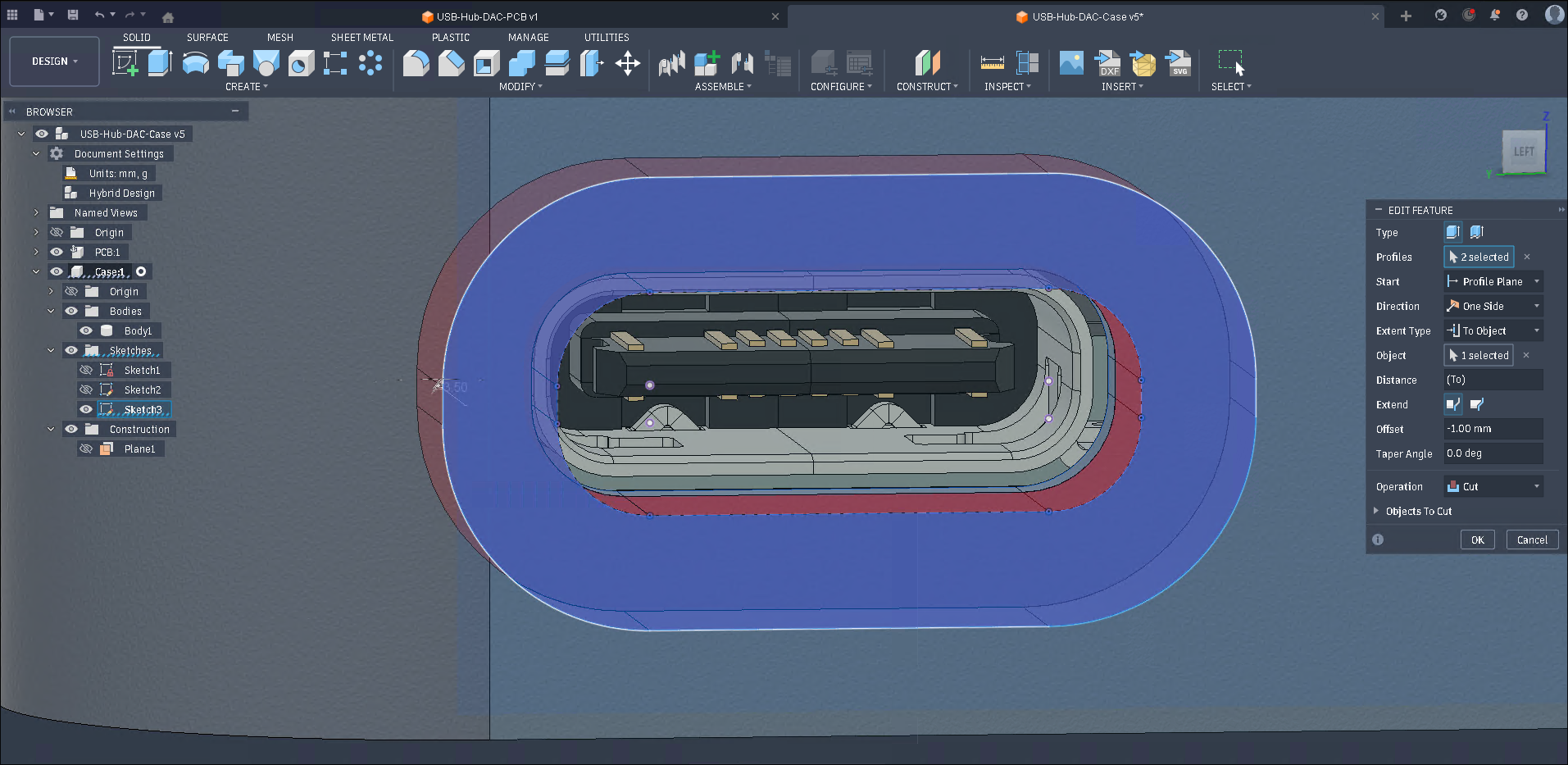
- Add fillets and any other details to the cutout.
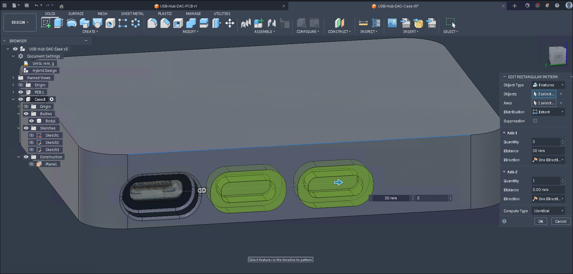
If you have multiple connectors in a row, you can then use the Rectangular Pattern tool. This lets you design everything about the port once and then duplicate all of the operations (the two extrudes and the fillet) in a row/grid. This is super useful since our goal is to repeat ourselves as little as possible so that we only have to change one thing and everything else automatically updates.
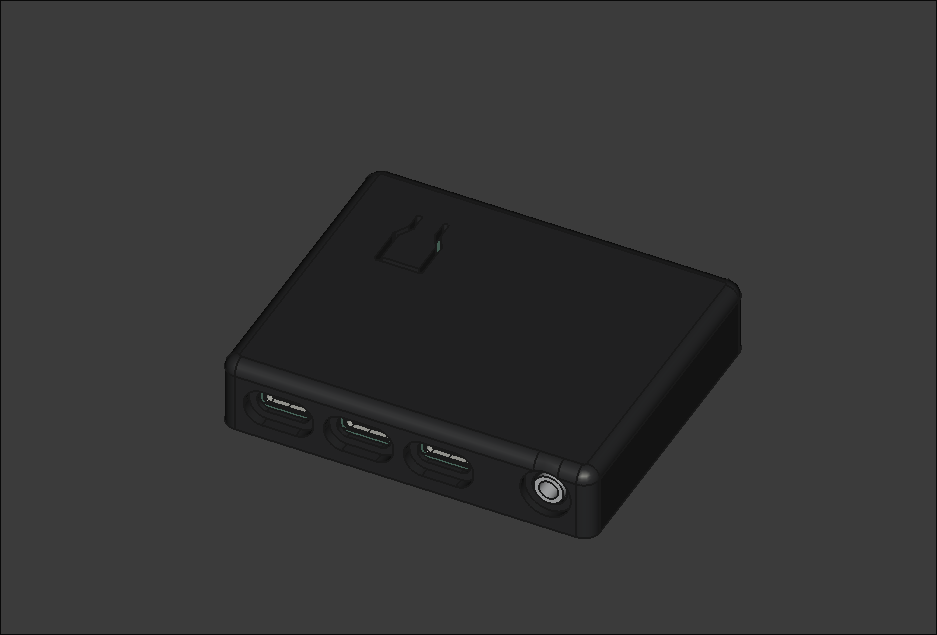
Repeat all of this for however many connectors you might have. You can go around and add fillets on edges and all of your other features like this integrated button I made for mute.
Mounting
Section titled “Mounting”We still need to attach the PCB to the case so let’s do that next:
- Create a sketch on the top of the inside of the case. Project your mounting holes from the PCB and then draw two circles centered on the original. Make one smaller at 1.9mm and one larger with a ~1.2mm larger radius than the previous (or you can make it larger if you have space). Do the same for all other mounting holes. (Instead of setting the dimensions for each circle, use the equal constraint!)
- Extrude the sketch using the
To Objectextent up to PCB.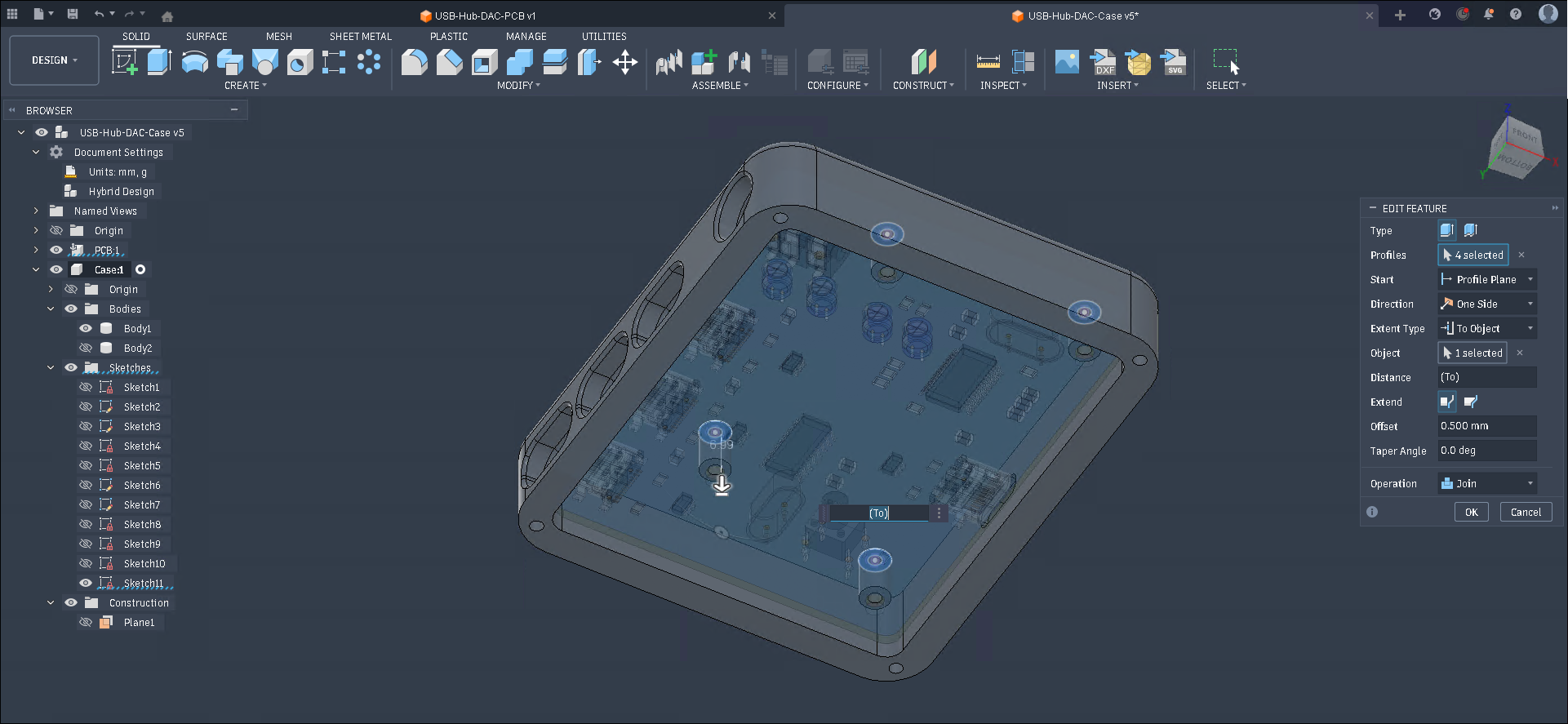
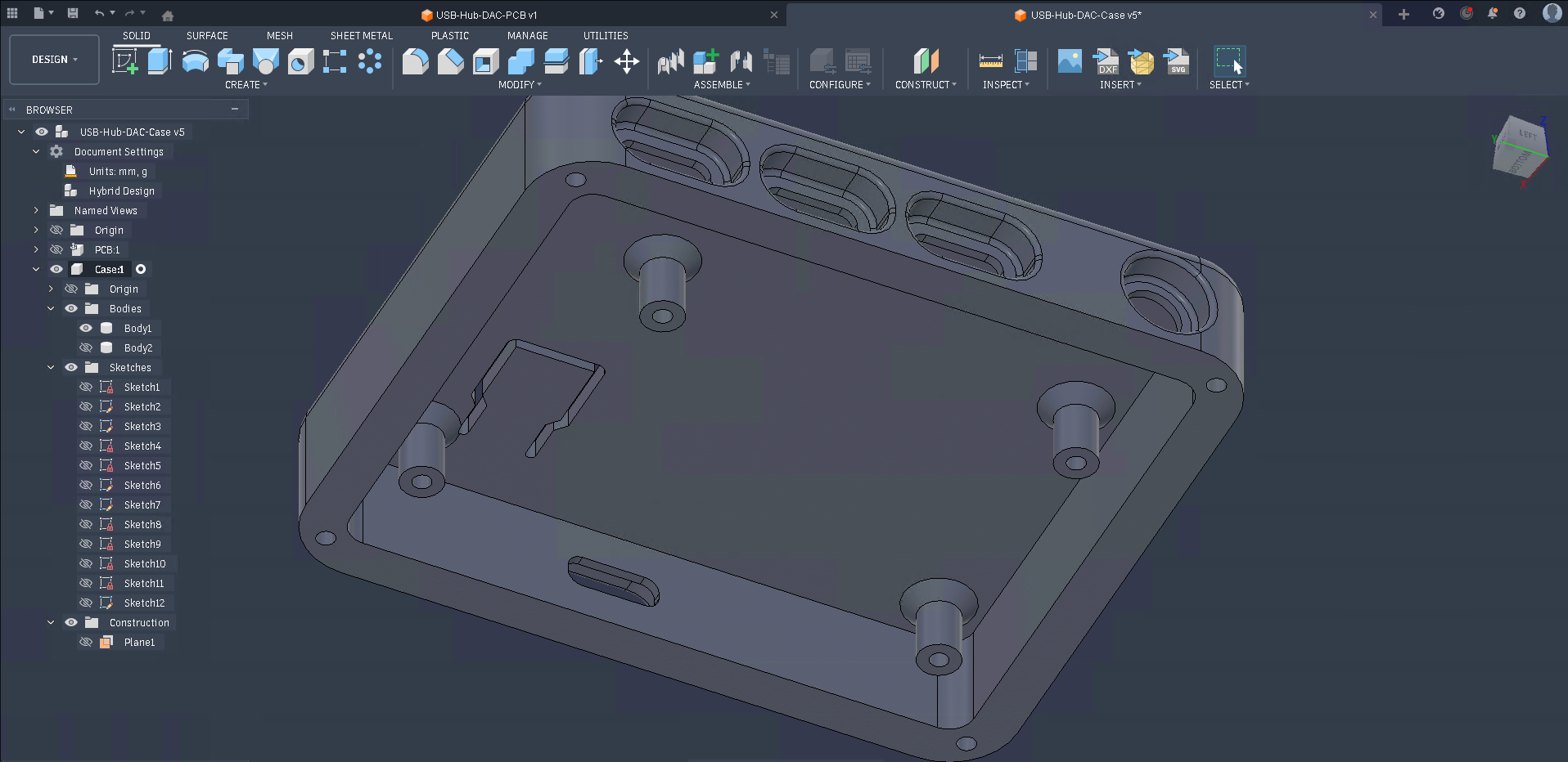
- Add chamfers to the base of the standoffs. Mine weren’t very big because the button tab was nearby but these can help to make it stronger since they will often break of right at the base.
Of course if you are designing a case that has a particular function you will need to adapt your design to work for your use case.
Decoration / Art / Polish
Section titled “Decoration / Art / Polish”At this point you have a case that is fully functional and could be used as is, but there is still a lot you can do to make it a ‘polished’ project. This guide was a simple example of how to make a case and you should add more to customize and make it your own.
This explains pretty well what polish is but basically it is all of the details that you can add to get it from a basic functioning project to something that looks like an original and complete ‘product’.
The orpheuspad is a great example of a polished project. All the edges are rounded/chamfered, it has accent colors, a logo, and in general looks like a finished project.
When you design something something, 6 months/a year later you should be able to look back and still think it was cool. You might have learned more and know that something could be better by doing it in a different way but you should never have to regret something because of a lack of effort. Perfection may be the enemy of finished but that doesn’t mean it should be rushed.
